
\(\newcommand{\cauchy}{\boldsymbol{\sigma}}\) \(\newcommand{\strain}{\boldsymbol{\varepsilon}}\) \(\newcommand{\uV}{\boldsymbol}\) \(\newcommand{\uT}{\boldsymbol}\) \(\newcommand{\defu}{\boldsymbol{u}}\)
HRR theory > Other HRR solutions
In the previous section, we have derived the expressions of the near-tip stress and strain fields for a mode I crack in plane-$\varepsilon$ state. Moreover an uncompressible material has been assumed. In this section, a brief summary is given for other HRR solutions that were derived in the literature:
- Plane strain deformation near a crack tip in a power-law hardening material, J. R. Rice, G. F. Rosengren, Journal of Mechanics and Physics of Solids 16 (1968), 1-12;
- Singular behaviours at the end of a tensile crack in a hardening material, J. W. Hutchinson, Journal of Mechanics and Physics of Solids 16 (1968), 13-31;
- Plastic stress and strain fields at a crack tip, J. W. Hutchinson, Journal of Mechanics and Physics of Solids 16 (1968), 337-347;
- Fully plastic solutions and large scale yielding estimates for plane stress crack problems, C. F. Shih, J. W. Hutchinson, Journal of Engineering Materials and Technology 98 (1976), 289-295;
- Requirements for a one parameter characterization of crack tip fields by the HRR singularity, C. F. Shih, M. D. German, International Journal of Fracture 17(1) (1981), 27- 43.
Mode I crack in plane-$\sigma$ state
Still assuming an uncompressible material, a similar analysis as in the plane-$\varepsilon$ state can be performed and yields different components tensors $\tilde{\cauchy} \left(\theta,n\right)$, $\tilde{\strain} \left(\theta,n\right)$, and $\tilde{\bf{u}} \left(\theta,n\right)$ fields.
Near-tip stress field
As we have derived in the previous section, the near-tip stress field reads
\begin{equation} \cauchy=\sigma_p^0\left(\frac{JE}{r\alpha\left(\sigma_p^0\right)^2I_n}\right)^{\frac{1}{n+1}}\tilde{\cauchy}\left(\theta,\,n\right) \, \text{.} \end{equation}.
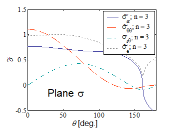
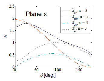
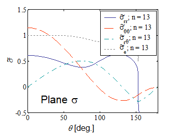
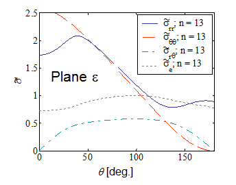
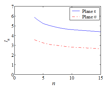
Pictures VIII.17-VIII.20 compare the stress shape tensor $\tilde{\sigma}$ components between plane-$\sigma$ and plane-$\varepsilon$ conditions for two different hardening parameters. Moreover the integral $I_n$ is reported in Picture VIII.21 for the two different cases. These figures allow comparing the difference in the crack tip loading, for instance through the asymptotic hoop stress $\sigma_{\theta\theta}$, between a plane-$\varepsilon$ and a plane-$\sigma$ states. Indeed, for the same value of the $J$-integral, and at the same crack tip distance $r$, the ratio between the two hoop stresses for two different hardening parameters are
\begin{equation} \frac{\left.\cauchy_{\theta\theta}\left(0,\,r\right)\right|_{n=3,\,\text{plane }-\varepsilon}}{\left.\cauchy_{\theta\theta}\left(0,\,r\right)\right|_{n=3,\,\text{plane}-\sigma}} \simeq\frac{1.9}{1.1}\left(\frac{3.86}{5.81}\right)^\frac{1}{4} = 1.56 \, \text{,} \end{equation} \begin{equation} \frac{\left.\cauchy_{\theta\theta}\left(0,\,r\right)\right|_{n=13,\,\text{plane}-varepsilon}}{\left.\cauchy_{\theta\theta}\left(0,\,r\right)\right|_{n=13,\,\text{plane}-\sigma}} \simeq\frac{2.6}{1.2}\left(\frac{2.87}{3.4}\right)^\frac{1}{14} = 2.13\,. \end{equation}
It can be seen that because the material cannot expend laterally, the crack tip is more loading in plane-$\varepsilon$ state, for the same value of the $J$-integral.
Process zone shapes
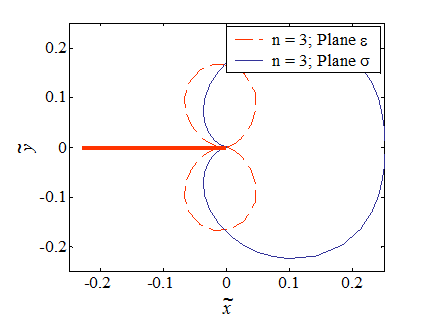
The process zone was defined as the zone in which $\sigma_e > \sigma_p^0$, whose boundary corresponds to $\sigma_e=\sigma_p^0$, and was found to be
\begin{equation} \tilde{r}\left(\theta,\,n\right) = \frac{\left(\tilde{\sigma}_e\left(\theta,\,n\right)\right)^{n+1}}{I_n} \, \text{.}\label{eq:processZone} \end{equation}
in terms of a non-dimensional radius $\tilde{r}= \frac{r \alpha \left(\sigma_p^0\right)^2 }{JE}$. The process zones for $n=$ are illustrated in Picture VIII.24 for the plane-$\sigma$ and plane-$\varepsilon$ states. It can be seen that the process zone is more diffuse in plane-$\sigma$ state.
Crack Tip Opening Displacement
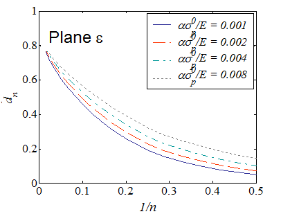
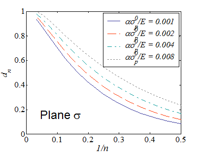
We have seen that there exists a direct relation between the crack tip opening displacement and the $J$-integral:
\begin{equation} \delta_t = d_n \frac{J}{\sigma^0_p}\,, \end{equation}
where $d_n$ depends on $n$ but also on the elastic strain of the considered material $\frac{\alpha\sigma^0_p}{E}$. The evolutions of $d_n$ in the cases of plane-$\varepsilon$ and plane-$\sigma$ states are respectively illustrated in Picture VIII.22 and Picture VIII.23.
Mode III crack loading
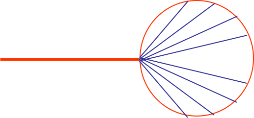
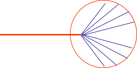
Assuming SSY, the process zone develops under mode III following a circular shape, as illustrated in Picture VIII.25 and Picture VIII.26 for respectively a perfectly plastic material and an elasto-plastic material with strain hardening.
Mode II and mixed mode crack loading
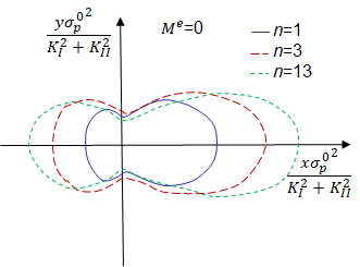
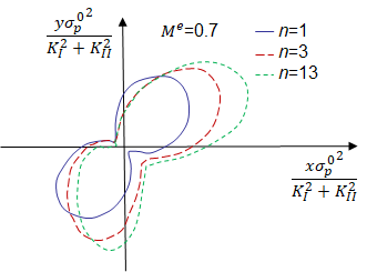
In SSY, the solution depends on the elastic mixity parameter given by
\begin{equation} M^e = \frac{2}{\pi}\arctan{\frac{K_I}{K_{II}}}\,, \end{equation}
which ranges from 0 (Mode I crack loading) to 1 (Mode II crack loading). Varying the mixity parameter the process zone changes orientation, from a"horizontal" shape in Mode II crack loading, as depicted in Picture VIII.27, rotating upward for a mixed mode crack loading as depicted in Picture VIII.28.
Compressibility effect
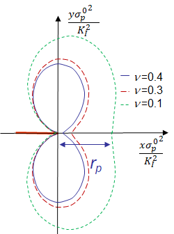
The HRR theory was obtained assuming an incompressible material. Using the finite element approach, it is possible to solve the problem with a real elasto-plastic law for which the elastic part follows a classical Hooke's law characterized by a Poisson ratio $\nu$. Considering a crack loaded in mode I under plane-$\varepsilon$ state and assuming SSY, the effect of the Poisson ratio on the process zone is depicted in Picture VIII.29. The plastic zone size $r_p$ is defined as the length of the plastic zone ahead of the crack tip, and increases with the material compressibility.
![]()