
Asymptotic Solution > Crack propagation
Toughness
In 1957 G. R. Irwin introduced a new failure criterion by crack propagation, which considers the SIFs defined in the asymptotic solution derived previously. In mode I this criterion reads
\begin{equation}K_I\quad\begin{cases} < K_{IC} \rightarrow \text{ the crack does not propagate,}\\ \geq K_{IC} \rightarrow \text{ the crack does propagate,} \end{cases}\label{eq:SIFCriterion}\end{equation}
where $K_{IC}$ is the mode I toughness. Under the LEFM assumption:
- $K_I$ depends on the geometry and loading conditions only,
- $K_{IC}$ depends on the material only.
The definition of the toughness and the way of measuring the fracture toughness have been summarized before. A brief summary of the way to evaluate the SIFs has also been presented and will be the object of a next lecture. We will conclude this lecture be reporting different features related to the SIFs in 3D.
3D front
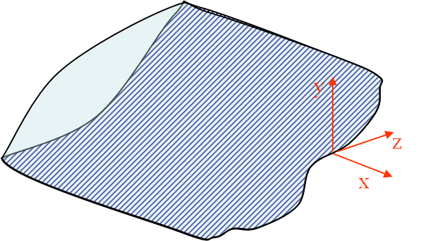
Until now only 2D solutions have been considered but a real crack is clearly 3D. In order to analyze a 3D crack front as in Picture II.33, at any point of the crack line:
- A local referential can be defined;
- Since the asymptotic solutions hold for $r \rightarrow 0$, at this distance the crack line seems straight and the problem is locally 2D.
- The crack tip field can be discomposed into 3 2D problems (3 2D modes).
Thickness effect
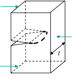
Near the border of a specimen the problem state is plane-stress (P-$\sigma$), while it is plane-strain (P-$\varepsilon$) near the center, where the triaxiality is higher. This means that the SIF is larger at the center as there are more constraints (no possible lateral deformations) (see HRR lecture). This has two consequences:
- The front propagates first at the center, see Picture II.34.
- The SIF measured at fracture is lower for a thick specimen as the P-$\varepsilon$ state dominates, see Picture II.35.
A crude approximation of the thickness $t$ effect on the measured toughness is
\begin{equation} K_{IC}\left(t\right) \simeq K_{IC}\left(t\rightarrow\infty\right) \sqrt{1+\frac{1.4}{t^2}\left(\frac{K_{IC}\left(t\rightarrow\infty\right) }{\sigma_p^0}\right)^4},\end{equation}
were $\sigma_p^0$ is the initial yield stress.
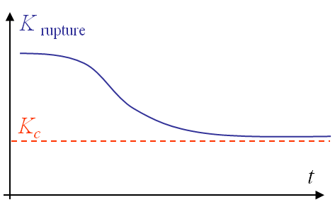
From this observation it appears that the toughness $K_{IC}$ is not dependent on the material only, as the thickness has an effect. To remain conservative, the toughness is defined as the measured value for a "thick-enough" specimen, see Picture II.35. Later in this class we will come back to this notion of "thick-enough".